
Marker-based and optically tracked 3D scanning can both deliver reliable measurement data—but they create different workflows. We explore how part size, preparation, access and working environment should guide the right choice.
When comparing industrial 3D scanning systems, attention often goes straight to specifications such as accuracy, resolution and measurement speed. These figures matter, but they do not tell you how the complete measurement process will work in practice.
One of the most important differences between scanning systems is how they track the scanner’s position as it moves around a component. Some handheld scanners use reference markers applied to the part or its surroundings. Other systems use a separate optical tracker to monitor the scanner in real time.
Both approaches can produce accurate, reliable measurement data. The difference lies in how they behave across different part sizes, environments and working conditions—and how much preparation is needed before scanning can begin.
Marker-based scanning is not an outdated technology, and optical tracking is not automatically the better choice for every application. The right system is the one that fits the scale of the work, the features being measured and the practical realities of where measurement takes place.
What do 3D scanning dots actually do?
A handheld 3D scanner captures a relatively small section of a component at any one time. As the operator moves around the part, the software must understand how each new section relates to the data already collected.
3D scanning dots—also known as reference markers or targets—provide fixed visual landmarks that allow the scanner to establish its position and orientation. By recognising several markers within its field of view, the system can align successive scans within a common coordinate system and build a complete three-dimensional dataset.
The markers do not measure the component themselves. Their role is to provide a stable reference network so the scanner knows where it is in relation to the part.
Depending on the application, markers may be applied directly to the component, placed on a surrounding fixture or distributed across a dedicated reference frame. The important requirement is that the marker network remains stable throughout the measurement. If the markers move independently of the part, the relationship between the captured data can no longer be trusted.
It is also worth distinguishing tracking markers from surface preparation. A marker-free optical tracking system may remove the need to place reference targets on the component, but reflective, transparent or otherwise optically challenging surfaces may still require scanning spray. Tracking and surface visibility solve two different problems.
When you’d choose marker-based scanning
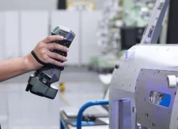
Marker-based handheld scanning is particularly effective for small and medium-sized components that can be covered with a manageable reference network. It provides a flexible, portable workflow without requiring a separate tracking unit to maintain sight of the scanner.
This can be a significant advantage when measuring complex parts, working within confined spaces or capturing recessed and difficult-to-access areas. Once the markers have established the reference network, the operator can move around the component without needing to maintain visibility between the scanner and an external tracker.
Compact marker-based scanners are therefore well suited to applications involving intricate castings, machined components, tooling, detailed assemblies and parts with narrow or restricted access. The scanner can be taken directly to the component, used around fixtures and moved through spaces where positioning a separate tracker would be difficult.
For repeat inspection, markers can sometimes be incorporated into a fixture or reusable reference frame, reducing the amount of preparation required for each part. Where the component size, working environment and inspection frequency are relatively consistent, this can create a highly efficient and repeatable process.
Most importantly, the use of markers does not make a system inherently less accurate or less advanced. For the right application, marker-based tracking can be the most practical and efficient approach.
What changes as components become larger?
The challenge with marker-based scanning is not that the fundamental technology stops working when components become larger. It is that the preparation and control required to maintain a reliable reference network increase with the measurement area.
A larger component requires more markers, and those markers must be positioned so that enough remain visible as the scanner moves around the part. Time must be allowed for applying them, checking their distribution and removing them afterwards where necessary.
As the reference network extends across a larger distance, small alignment uncertainties can also accumulate. Large-scale marker-based measurement may therefore require an additional photogrammetry process to establish and control the reference network across the complete component.
Photogrammetry can significantly improve stability over larger measurement areas, but it becomes another stage in the workflow. The complete process may now include marker preparation, photogrammetry, scanning, data alignment, analysis and reporting.
This does not mean marker-based scanning cannot be used successfully on large components. It means that the full workflow—not simply the scanner’s headline measurement speed—needs to be considered.
A system capable of capturing millions of measurements per second will not necessarily produce the fastest overall process if preparing the component takes longer than collecting the data. This becomes particularly important for repeat inspection, high-mix production or applications where parts regularly change in size and geometry.
How does an optical tracker change the workflow?
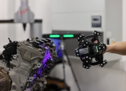
An optically tracked scanning system uses a separate tracking device to monitor the position of the handheld scanner.
Instead of relying on reference markers distributed across the component, the tracker recognises a calibrated pattern built into the scanner. It continuously follows the scanner’s position and orientation, allowing the captured surface data to be placed within a common coordinate system as the operator moves.
Because the tracker is following the scanner, reference markers do not normally need to be applied to the component. This is what is generally meant by marker-free or target-free 3D scanning.
Systems such as NIMBLETRACK Gen 2 combine a handheld scanner with a portable optical tracker, allowing components to be measured without covering the surface in reference targets. Both units are wireless, which further reduces the amount of equipment and cable management around the measurement area.
Removing marker preparation can make a substantial difference when components are large, when multiple different parts are measured or when the same inspection needs to be repeated regularly. It may also be valuable where adhesive markers cannot be applied directly to a finished, sensitive or high-value surface.
However, optical tracking introduces its own practical consideration: the tracker needs suitable visibility of the scanner. If the operator moves behind the component, enters a confined area or scans a feature hidden from the tracker’s view, the tracking position may need to be adjusted. Very large or obstructed measurement areas may require tracker repositioning, planning around the component or, in some systems, additional trackers.
An optical tracker also has a defined measurement volume. The relevant question is not simply how accurate the scanner is at close range, but how the complete system performs across the distance and volume required by the application.
Swipe across the table to compare both workflows.
| Compare | Compact and flexible Marker-based scanning The scanner uses a stable network of reference markers. | Marker-free on the part Optically tracked scanning An external optical tracker follows the scanner in real time. |
|---|---|---|
| Tracking method | Reference markers are placed on the component, fixture or surrounding reference frame. | A separate optical tracker monitors the scanner’s position and orientation. |
| Part preparation | Markers must be positioned and managed, although reusable fixtures or reference frames can reduce preparation. | Markers are not normally required on the component, reducing preparation for suitable applications. |
| Equipment | Primarily the handheld scanner, computer and any required reference markers or scale-control equipment. | Handheld scanner, optical tracker, computer and the tracker’s supporting equipment. |
| Access around the part | Does not require visibility to a separate tracker, making it useful for confined, recessed or obstructed areas. | The tracker must maintain suitable visibility of the scanner throughout the measurement. |
| Best suited for | Small and medium-sized components, fine detail and applications where access is restricted. | Repeat measurement, larger or more varied components and applications where marker preparation adds significant time. |
| Scaling to larger parts | Requires an extended marker network and may require photogrammetry to control accuracy across larger distances. | Operates within a calibrated tracking volume, with tracker positioning planned around the required measurement area. |
| Repeat inspection | Efficient where markers can remain on a reusable fixture or reference frame. | Can reduce repeated preparation when different components are measured frequently. |
| Surface preparation | Scanning spray may still be required for reflective, transparent or otherwise challenging surfaces. | Marker-free tracking does not remove the possible need for scanning spray on challenging surfaces. |
Neither method is universally better. The right approach depends on part size, access, measurement frequency, working environment and the level of control required across the complete measurement volume.
This comparison shows why the decision cannot be reduced to “markers or no markers”. Each method changes where the preparation happens and which practical constraints need to be managed.
When does marker-based scanning make sense?
Marker-based scanning is likely to remain the most appropriate option when:
- Components are generally small or medium-sized
- Fine detail and restricted access are important
- The operator needs to move into areas that would be hidden from an external tracker
- Marker preparation is quick relative to the overall measurement process
- A single compact handheld system is preferable
- Existing fixtures or reference frames already support an efficient marker workflow
- The current system consistently meets the required tolerance and measurement objective
In these circumstances, moving to an optically tracked system may add equipment without creating a meaningful improvement in the overall process.
When does optical tracking make sense?
An optically tracked system becomes particularly relevant when:
- Applying and removing markers is becoming a significant part of the measurement time
- Components are becoming larger or more varied
- The same measurement needs to be repeated frequently
- Markers cannot be applied directly to the component
- The scanner regularly moves between the inspection room, shop floor and site
- The business wants to reduce preparation between different jobs
- The required measurement area fits within a practical tracker setup
- A wireless, marker-free workflow would improve access, mobility or safety
The potential benefit is not simply that the system scans faster. It is that the complete process—from preparing the component to collecting usable data—may become more efficient.
Start with the measurement requirement, not the technology
It is tempting to compare 3D scanning systems using a single specification or feature, but the right choice depends on the complete measurement task.
Part size matters, but so do access, surface condition, feature type, working environment, inspection frequency and the tolerance of the decision being made. A system used to capture detailed geometry inside a compact assembly is solving a different problem from one used to inspect large fabrications on the shop floor.
The most useful questions to ask include:
- What are the typical and maximum component sizes?
- How much time is currently spent preparing each job?
- Can the component accept adhesive markers?
- Will an external tracker have a practical line of sight?
- Where will the measurement take place?
- Which features and tolerances must be verified?
- Is the work occasional, repetitive or high-mix?
- What happens if the measurement decision is wrong?
These questions reveal far more about suitability than measurement speed alone.
One method is not universally better
Marker-based and optically tracked systems solve the same fundamental problem in different ways: maintaining a reliable understanding of the scanner’s position as it moves.
Marker-based scanning provides compactness, flexibility and excellent access within smaller measurement volumes. Optical tracking can reduce component preparation and simplify the workflow as parts become larger, more varied or more frequently measured.
For some businesses, an optically tracked system will represent a natural progression as their applications expand. For others, a marker-based scanner will continue to provide exactly the capability they need. The two approaches can also complement one another, with each system used for the type of work it handles best.
The objective is not to remove markers from every scanning process. It is to identify whether the tracking method supports the way your business measures parts today—and how that work may be changing.
If you are reviewing your current 3D scanning workflow, T3DMC can help you compare the practical implications of marker-based and optically tracked systems using your own components, tolerances and working environment.