
Optical tracking can remove a significant amount of preparation from 3D scanning—but that does not mean every marker-based workflow needs to change.
The clearest signs often appear when components, applications or working environments begin to outgrow the process originally put in place.
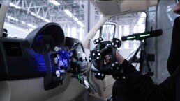
When a business first adopts handheld 3D scanning, the workflow is normally built around the parts and applications it needs to measure at that time. A compact marker-based scanner may provide exactly the right balance of portability, access and measurement capability. Applying a manageable number of reference points is simply part of preparing the job.
Over time, however, the work rarely stands still. Components become larger. The range of jobs expands. Measurement moves beyond the inspection room and onto the shop floor or out to customer sites. A process that once felt quick and uncomplicated can gradually accumulate additional preparation, equipment and operator decisions.
This is where optical tracking becomes worth considering—not because marker-based scanning has suddenly become outdated, but because the complete measurement workflow may have changed.
If you would first like an explanation of how the two tracking methods work, read our guide to marker-based and optically tracked 3D scanning. Here, we focus on the practical signs that an optically tracked system may now fit the application more effectively.
Your components are increasing in size
Part size is one of the most obvious reasons to review the tracking method, but the important issue is not simply whether a marker-based scanner can capture a larger component. In many cases, it can. The question is what must be added to keep the process controlled as the measurement area expands.
A marker-based scanner establishes its position using a stable network of 3D scanning dots, also known as reference markers or targets. As the scanner moves, enough dots must remain visible for it to understand how each new section of data relates to the area already captured.
Larger components therefore require a wider marker network. More time may be needed to distribute the dots, check their spacing, extend the network around the component and remove them when the work is complete. For sufficiently large measurement areas, photogrammetry may also be introduced to control the network and reduce the risk of accumulated alignment uncertainty over distance.
None of this makes large-scale marker-based scanning invalid. With the right planning and photogrammetry process, it can remain highly effective. It does mean, however, that the preparation surrounding the scan becomes a more significant part of the job.
An optically tracked system changes where that control comes from. Instead of building a reference network across the component, a separate calibrated tracker follows the handheld scanner within its measurement volume. Markers are not normally required on the part, so increasing component size does not automatically create the same increase in dot application and management.
The trigger for reviewing the workflow is therefore not a particular dimension. It is the point at which scaling the marker network begins to create disproportionate preparation, complexity or uncertainty relative to the measurement itself.
The work now includes a greater variety of parts
A stable, repeatable marker process can be extremely efficient when the same type of component is measured regularly. Reference dots may remain on a reusable fixture or frame, preparation can be standardised, and operators become familiar with the best scanning route.
The calculation changes when the workload becomes more varied.
A high-mix environment may involve small machined parts one day, a large fabrication the next and a customer component with a completely different geometry after that. Each job can require a new decision about marker quantity, placement, accessibility and whether the component surface can accept adhesive dots.
This variation makes preparation harder to standardise. The operator is not simply repeating a proven process; they are planning a new reference network for each job. Even when each individual setup is manageable, the cumulative time spent adapting between applications can begin to affect throughput.
Optical tracking can provide a more consistent starting point across that range of work. The tracker still needs to be positioned for the required measurement area, but the team is no longer creating a new marker network across every component. That can make it quicker to move between different jobs and reduce the amount of consumable preparation associated with high-mix measurement.
This does not mean optical tracking will suit every feature on every part. Restricted or deeply recessed areas may still favour a compact marker-based scanner that does not need to remain visible to an external tracker. The benefit appears when greater consistency between varied jobs outweighs the additional tracker setup.
Preparation is taking too much of the total measurement time
Scanner specifications tend to emphasise measurement rate, frame rate and the speed at which surface data can be captured. Those figures are important, but they represent only one part of the process.
The more useful measure is the total time from receiving the component to producing usable measurement data. That may include cleaning or preparing the surface, applying scanning dots, establishing a larger reference network, configuring the equipment, capturing the data and removing markers afterwards.
If the scan itself takes only a few minutes but preparation takes considerably longer, improving capture speed alone will not transform the overall workflow. The greater opportunity may be to reduce what happens before data collection begins.
This becomes especially relevant when parts are inspected repeatedly or measurement is supporting production decisions. A preparation stage that seems acceptable for an occasional job can become a meaningful constraint when repeated several times a week, across multiple components or under pressure from production.
Optical tracking removes one of those recurring stages by allowing the tracker to reference the scanner directly. The potential saving should therefore be assessed across the complete process, rather than treated simply as the time required to apply dots to one part.
A useful exercise is to record preparation, scanning and reporting time separately across several representative jobs. This provides a clearer view of where the real bottleneck sits and whether changing the tracking method would materially improve throughput.
The marker network has become a process in its own right
There is a practical difference between applying a straightforward group of scanning dots and managing a large, controlled reference network.
As the network expands, operators need to consider coverage, stability and continuity around the complete measurement area. If the part or its surrounding references move independently during scanning, the relationship between the captured data can no longer be trusted. When photogrammetry is required, scale control and an additional capture stage also become part of the method.
These are valid metrology controls, not unnecessary complications. The issue arises when maintaining them begins to demand a level of planning that no longer fits the required pace or environment.
Optical tracking replaces the part-based network with a calibrated tracking volume. This can make the workflow easier to reproduce, particularly when the same tracker arrangement can cover a range of components within a defined area.
It is important not to oversimplify the alternative. The tracker must maintain suitable visibility of the scanner, and its position needs to support the features and sides of the component being captured. Obstructions, enclosed areas or work around the back of a large component may require the tracker to be repositioned or the scan strategy to be planned in stages.
Optical tracking therefore does not remove the need for measurement planning. It changes what needs to be planned—from the placement and control of a marker network to the position, visibility and calibrated volume of the tracker.
The component has complex freeform surfaces
Complex freeform surfaces can make marker-based scanning more demanding, even when the overall component is not especially large. As the scanner moves across deep curves, dips and rapidly changing faces, it must continue to see enough scanning dots within its field of view to maintain reliable tracking.
Creating that continuity can require careful marker placement across several different orientations, particularly on moulds, composite parts and components with pronounced changes in depth or curvature.
With optical tracking, the external tracker follows the scanner directly rather than relying on a continuous network of dots across the component. This can simplify the capture of complex freeform geometry, provided the tracker can maintain suitable visibility of the scanner throughout the measurement.
Measurement is moving between different environments
Portable 3D scanning is increasingly used wherever the component happens to be: in the inspection room, beside a machine tool, on the shop floor, outdoors or at a customer’s site. Moving measurement closer to the part can reduce component handling, transport and delays, particularly when parts are large, heavy or difficult to relocate.
It can also expose weaknesses in a setup that was originally designed for a single controlled area.
Cables need to be routed safely. Power and network access may not be available in the most convenient position. Different components can require the laptop, scanner and supporting equipment to be moved repeatedly. Marker application may also be more difficult where surfaces are dirty, hot, sensitive, difficult to reach or exposed to changing site conditions.
A wireless optically tracked system can create a more mobile measurement setup by reducing cables around the operator and removing the normal requirement to place markers on the component. Systems such as NIMBLETRACK Gen 2 use a wireless scanner and tracker, allowing the equipment to be taken from the lab to the line or field without rebuilding the same connected setup around every job.
Portability does not remove the principles of metrology. Temperature, vibration, part stability, surface condition, tracker placement and the required tolerance still need to be considered. A system being wireless or easy to move does not make the surrounding measurement process automatically controlled.
The benefit is practical flexibility: fewer physical restrictions around where the equipment can be positioned and less part preparation when moving between different environments.
You need a more flexible measurement setup
Flexibility can mean different things depending on the application. For one team, it may mean moving quickly between the inspection room and production. For another, it may mean measuring parts that vary significantly in size. It may also mean reducing the number of consumables and cables required around a busy working area.
An optically tracked system can support this by separating scanner positioning from a reference network applied to the component. Within the tracker’s suitable working volume, the operator can move around the part while the system maintains the relationship between scanner and measurement area.
However, marker-based scanning has its own form of flexibility. A compact handheld scanner can be easier to take into confined, recessed or obstructed spaces because it does not need to maintain visibility to a separate tracker. For smaller components, applying a simple set of dots may also be faster than positioning additional equipment.
The decision is not therefore between a flexible and an inflexible technology. It is about which form of flexibility matters most for the work being done.
If access around complex features is the main challenge, marker-based scanning may remain the stronger option. If preparation, part variation and movement between jobs are becoming the bigger constraints, optical tracking may offer the more adaptable complete workflow.
Questions that can reveal whether the workflow has changed
Rather than starting with a scanner specification, review several recent and representative measurement jobs and ask:
- Are the components becoming larger than those the original process was designed around?
- How much time is spent applying, checking and removing 3D scanning dots?
- Is photogrammetry now required for a growing proportion of the work?
- How often does the team change between different component sizes or geometries?
- Can markers be applied safely and appropriately to every surface being measured?
- Does the equipment regularly move between the lab, shop floor and customer sites?
- Does the component include deep curves, dips or changing faces that make marker visibility difficult to maintain?
- Are cables, available power or equipment positioning restricting where measurement can take place?
- Would an external tracker have suitable visibility of the scanner around the required features?
- Is the current process still meeting the required throughput and decision times?
The answer to any single question will not determine the correct technology. Together, they show whether the existing tracking method still supports the way measurement is actually being used.
What optical tracking does—and does not—remove
Optical tracking can remove the normal need to apply reference dots to the component, but it does not eliminate every form of preparation.
Reflective, transparent, very dark or otherwise optically challenging surfaces may still require scanning spray. Tracking and surface visibility address different issues: the tracker establishes where the scanner is, while surface preparation helps the scanner capture the component itself.
The component must still be stable. The measurement strategy, alignment method, required features and reporting process must still be defined. The system also needs to be verified for the intended measurement volume, environment and tolerance.
This distinction matters because the objective should not be to create a process with no preparation at all. It should be to remove preparation that no longer adds value while retaining the controls required to produce reliable measurement data.
Review the workflow, not only the scanner
Optical tracking makes the most sense when it solves a practical problem in the complete measurement process. Increasing part sizes, greater variation between jobs, time spent applying scanning dots, complex marker networks and movement between environments are all signs that the balance may have shifted.
For some businesses, this will make an optically tracked system the natural next step. For others, a marker-based scanner will continue to offer the most efficient combination of compactness, access and capability. The two technologies can also complement one another, with each used for the work it handles best.
The most useful comparison is not whether one scanner captures data faster than another. It is how long each complete workflow takes, what practical constraints it introduces and whether it produces results that can be trusted for the decision being made.
If your applications have changed since your current scanning process was introduced, speak to a T3DMC expert. We can review your parts, working environment and measurement requirements to determine whether optical tracking would create a meaningful improvement.