
The part is in front of you, but the CAD you need is missing. Discover how 3D scanning and reverse engineering can give you a practical starting point for replacement, modification and design work.
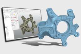
You need to replace a component, adapt a fitting or develop a design around an existing assembly. You have the physical part, but no suitable CAD. Recreating its geometry by hand could take considerable time, particularly where curved surfaces and awkward features are involved.
This is where reverse engineering with 3D scanning can help. By capturing the component’s surface geometry, you can build a digital reference for the modelling work that follows. Your team starts with information from the part itself, making it easier to understand its shape and develop the geometry you need.
The next question is what that finished model should let you do. Checking whether something fits into an available space calls for a different output from redesigning a mounting arrangement. Understanding that distinction helps you choose a scan-to-CAD workflow that suits the job.
What do you need to do with the finished model
“We need CAD” can mean several things. A maintenance engineer may need a model for manufacturing a replacement. A designer might want to change a component’s dimensions. Someone reviewing an installation may simply need its external shape.
Each requirement involves a different amount of modelling. Starting with the intended use helps keep the work focused, so effort goes into the geometry that matters rather than details the project will never use.
It also makes conversations with colleagues or a scanning partner more productive. Instead of specifying a file alone, explain the task: “We need to move these mounting holes while keeping the surrounding shape.” That gives everyone a much clearer picture of the result.
Understanding mesh surface and parametric models
A scan usually provides surface data that can be processed into a mesh: a digital representation made up of connected facets, commonly triangles. A mesh file such as STL may be all you need for a space check or another task in software that supports it. It is also a useful reference for reconstructing CAD.
For engineering work that needs defined surfaces or a solid body, the geometry can be rebuilt from that reference. Planes, cylinders and more complex curved surfaces are created to describe the component. STEP and IGES are common formats for transferring reconstructed geometry into other CAD packages.
If you expect to make repeated design changes, a parametric model may be useful. Features such as holes, extrusions and patterns are controlled through dimensions and relationships, helping the designer make structured edits.
The useful distinction is how you will work with the model. A STEP solid may support direct editing in your CAD system, but it does not automatically include the original feature history. Trying a typical edit on a sample file is a straightforward way to establish whether the proposed output gives you the flexibility you need.
Reverse engineering gives you the opportunity to improve the part
An existing component tells you how it looks today. That can include years of wear, damage or changes made during service. When creating a replacement, you have an opportunity to decide which details to preserve and which to restore or redesign.
Consider a cast housing with a worn bore and a machined mounting face. Capturing the outer shape gives the modeller a reference for the casting, while the bore may need rebuilding to an agreed nominal size. Available drawings, the mating component or other engineering evidence can help establish that dimension.
This is where engineering knowledge adds value to the scan. The modeller can retain the shape needed to fit the installation while building the functional features around the replacement’s requirements. Discussing those choices early helps produce a model suited to its next job, with any assumptions clearly recorded.
Capture the geometry that matters to your project
Knowing the intended use also helps plan the scanning. For a marine fitting, the mounting face and connections may be just as important as its overall shape. For a vehicle component, access around the assembly may shape how the capture is carried out.
A handheld scanner can approach a component from different angles, giving flexibility around complex surfaces. Deep cavities and concealed features need particular attention because optical scanning relies on seeing the surface. Repositioning the part, removing an obstruction or adding a complementary measurement may provide the information needed.
The aim is a useful reference for modelling. Reviewing the important surfaces and interfaces before capture helps avoid a return visit for missing information. Where a surface has to be reconstructed across a gap, it should be clear which geometry was measured and which was inferred.
Turning the scan into CAD your team can use
Once the geometry has been captured, the reverse engineering work moves into modelling. This can involve preparing and aligning the mesh, extracting sections, fitting geometric features and building the surfaces or solid required for the project.
For suitable applications, 3DeVOK MT Gen2 with QuickSurface brings these stages together into a scanning and modelling route. The scanner captures the physical geometry, while QuickSurface reverse engineering software provides tools to reconstruct CAD from that reference. The work can combine straightforward engineering features with more complex freeform shapes.
Modelling takes time and judgement, and its scope depends on the deliverable. A simple reference surface and a feature-based model for redesign involve different work. Allowing for that stage, the skills involved and the handover into your CAD software gives you a clearer view of the complete process.
Build confidence in the finished CAD
Comparing the reconstructed model with the scan shows how closely it follows the captured component. Sections, dimensions and surface comparisons can help review the areas that matter, including any deliberate changes made to restore worn geometry.
For a replacement part, that comparison sits alongside the checks needed for its intended use. A mounting interface may need dimensional verification; a redesigned feature may need further engineering validation. The important thing is to connect those checks to the job the model will support.
A useful handover includes geometry that works in your software, clarity about any assumptions and the ability to carry out the next design operation. That is when the scan becomes a practical starting point for moving the project forward.
Have a part but need usable CAD
If missing CAD is holding up a replacement or design project, we can help you explore a suitable reverse engineering route. Share a photograph, drawing or existing dataset and tell us what you want to do with the finished model.
At T3DMC, we can talk through the capture, modelling and software requirements with you, helping you identify a practical way from the component you have to the CAD you need.