Modern Machine Shop online recently posted an interesting article telling the story of James Pershken from Cincinnati, a company who manufacture 3D printers and more. Pershken manages the CMM inspection of machined parts for the company’s 3D printers, and tells Modern Machine Shop how 3D printing fixtures has helped to make his 3D scanning process simpler – “A lot of the motivation for me personally was that we were such a small operation,” James Pershken says. “Basically everyone is trying to do a lot of things, and it really helped me kind of offload some of this monotonous work from my plate and be able to help out in other areas.”
At The 3D Measurement Company, we know that 3D printed fixtures are a great way of ensuring that you have optimised and repeatable measurements using 3D Optical scanning systems as well as traditional CMM technology. We use this type of 3D Printed design within our 3D scanning process for some of our complex customer projects where we perform gauge R&R and fixture repeatability checks as part of our inspection and measurement protocols.
Our customer requirements for repeatable and stable measurements have led to the development of in-house fixture design and mounting systems for a variety of different size and shape of parts and our 3D printer is a great asset for the production of parts for our 3D scanning process for these projects. We have combined this with the largest open source 3D optical scanning facility in our temperature stable headquarters to provide a full service 3D scanning and fixture development for our growing group of valued customers. For more information on this type of 3D scanning or 3D printed fixtures or design, please do not hesitate to contact us on info@t3dmc.com or give our team a call on 01746 762251 and we will be happy to discuss them with you
“A lot of the motivation for me personally was that we were such a small operation,” James Pershken says. “Basically everyone is trying to do a lot of things, and it really helped me kind of offload some of this monotonous work from my plate and be able to help out in other areas.”
Mr. Pershken is not talking about robotics or sophisticated software here, but something a little less obvious: fixturing for coordinate measurement machine (CMM) inspection. As a mechanical quality engineer at Cincinnati Inc. (CI), he manages the CMM inspection of machined parts for the company’s 3D printers. The benefits outlined above came from actually using those very same 3D printers to make custom CMM fixtures that, in turn, support the manufacture of new printers.
New Valence Robotics (NVBots for short) was a Boston-based manufacturer of polymer 3D printers, founded by a group of Massachusetts Institute of Technology engineers and acquired by CI in late 2017 to form the NVBots Business Unit. According to NVBots founder AJ Perez, the company was started in 2014 with a focus on automating and streamlining 3D printing by connecting printers to the cloud and optimizing engineering workflow. Its NVPro 3D printer was rebranded by CI as the Small Area Additive Manufacturing (SAAM) machine in 2016. Mr. Pershken now works in the NVBots Business Unit within CI.
CI SAAM 3D printers feature a number of machined components that require CMM inspection. Pershken uses an entry-level CMM that has to be programed by manually moving the probe to identify the datums so that the machine can determine the part axes and execute the program correctly. For a part that uses conventional off-the-shelf fixturing, it takes time and a fair bit of skill to set up a part on the table and then to perform the manual hits with the probe.
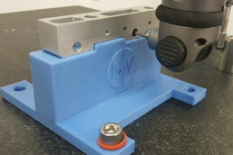
3D Printer Parts, 3D-Printed Fixtures
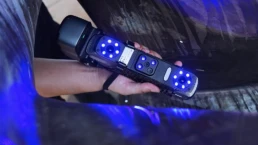
While working with one fairly complex machined part, Mr. Pershken had the idea to 3D print fixtures instead of using off-the-shelf items and a pegboard. That part (pictured above) is an aluminum bearing block that goes into the 3D printer gantry. Two slots hold the idler bearings around which the belt is routed. The components like this that make up the 3D printer frame are the most critical to measure correctly because they most directly affect how accurate the final printer will be, he says. On this bearing block, the tightest tolerance is a roughly 30-micron window for the pin that supports the bearing.
In inspection, the bearing block needed eight hits in each axis for a total of 24 manual hits. “One day I was just sick of putting the manual datums in again,” Mr. Pershken says. This frustration led him to create plastic fixtures using an CI SAAM 3D printer that would hold the part instead.
To design this fixture for 3D printing, Mr. Pershken says he “hacked” the injection-mold environment of a CAD program to create one half of a mold that could positively retain the part. To make the mold design work as a fixture, he then removed some material and added features such as a standard base that would fit on the CMM table.
The 3D-printed fixture is designed to allow parts to drop in place without clamps or screws. To hold the bearing block, Mr. Pershken made use of one of its features: a long slot, visible in the photo above. The mold-design software generated a solid protrusion to fill this slot, but Mr. Pershken split it into four pieces. When 3D-printed in polylactic acid (PLA) thermoplastic, this feature has enough flex to hold the part securely in place without marring it. As a result, the fixture only obscures one noncritical face of the bearing block, enabling Mr. Pershken to measure the remaining five faces with one fixturing setup.
“I can just load them up, hit ‘go’ and do some other work while it’s running.”
Setting up the 3D-printed fixture simply required calibrating the CMM probe on the reference sphere, mounting a bearing block on the fixture, and then measuring all three planes manually to give the machine a reference point and direction. Subsequent parts can then be placed and measured with the press of a button. Parts placed on a 3D-printed fixture are not going to be in exactly the same position every time, but they do not need to be. “As long as it’s close enough and the CMM gets the part datums correctly, it’ll run just the same,” Mr. Pershken says. “I can just load them up, hit ‘go’ and do some other work while it’s running.”
Saved Effort and Reduced Cost
With cycle times of just a few minutes (it takes only 1 to 2 minutes for the CMM to measure the bearing block for instance), a 3D-printed fixture is “not a huge time saver,” Mr. Pershken says, “but it is a huge effort saver.”
Fixturing the parts conventionally would involve the use of a fixture kit, which may cost $1,000 for a basic option, and it would not be a drop-in-place solution. “You’ll have to introduce a clamping force somewhere,” Mr. Pershken says, which runs the risk of damaging the part. “It’s going to require somewhat more of a skilled operator and little more time in the setup.”
Improving future 3D scanning projects
Mr. Pershken now has a collection of about 10 3D-printed fixtures, some of which have been in use for as long as 2 years without needing replacement. Since the fixtures essentially get checked automatically with each CMM cycle, Mr. Pershken tests them periodically but has not found a need to worry much about loss of accuracy. “I haven’t noticed any slop in them or any bad measurements,” he says. “I haven’t had to replace one yet.”
Many of the machined parts for the CI SAAM printer are fairly simple cylinders and plates that would not benefit much from a custom 3D-printed fixture. However, for those that have an intermediate to complicated geometry and require high accuracy, such as parts for the 3D printer frame, the 3D-printed fixtures simplify the CMM process significantly. As CI begins to produce more of its printer parts through machining and sheet-metal forming, Mr. Pershken plans to continue 3D-printing fixtures to support CMM inspection and improve the 3D scanning process.”