Advancedmanufacturing.org recently published a great article about how “Formula SAE competitions challenge teams of University undergraduate and graduate students to design and fabricate a small, formula-style vehicle” and how 3D scanners played a huge part in producing the necessary CAD models used to facilitate the process.
The 3D Measurement Company have supported similar projects to this one in the UK so if you need 3D scan data and CAD reverse engineering services for your project, please contact us on 01746 762251 or via email on info@t3dmc.com.
Read the full article from Advanced Manufacturing, below or on their website
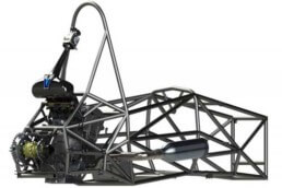
Formula SAE competitions challenge teams of university undergraduate and graduate students to design and fabricate a small, formula-style vehicle. Once completed after eight to twelve months of work, the vehicles are judged in a series of static and dynamic events including technical inspection, cost, presentation, and engineering design, solo performance trials, and high-performance track endurance. Space constraints within the cars are such that accurate CAD models of the engine’s external geometries are needed. Engine manufacturers will not provide design data so 3D scanners are used to create the CAD files.
For the University of Connecticut FSAE team’s entry for a Formula SAE Michigan competition, Bolton Works (East Hartford, CT) provided advanced reverse engineering to make 3D CAD models in Solidworks of a Suzuki GSX-R600 engine. The CAD models are used to check for interference and to facilitate design modification of the engine. The use of 3D scan equipment to make CAD files is not new within the FSAE student community, but improvements in 3D scanning have streamlined the process.
To provide UConn with a comprehensive 3D scan model, Bolton Works determined that an industrial-grade, high-resolution Zeiss Comet scanner with high-end optics and sensors needed to be used to ensure detail and accuracy. The accuracy of critical dimensions of the CAD model should be verified with a Zeiss Contura CMM. The engine model should include all factory bolted-on accessories of the engine, and the model should be subdivided into its 25 individual components so they can be replaced by an UConn designed one in Solidworks, as needed. Internal geometry of the complete cylinder head’s flow path should be provided.
The Suzuki GSX-R600 engine comprises four load-bearing components: die-cast aluminium lower crank case, which includes the upper transmission case; cast aluminium cylinder block with integrated upper crank case; cast aluminium cylinder head; and de-cast lower transmission case. Bolted to these four components are covers for the clutch, stator, camshafts, vents, crankcase and sprocket, as well as an external water pump assembly, the starter motor, oil filter, oil cooler, water inlet housing and several sensors. Twenty-five components have surfaces external to the engine and all were scanned and modelled to become part of the Solidworks assembly.
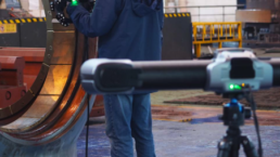
There are various techniques for the measurement of a three-dimensional shape. One method is “structured light projection.” As white light or blue light can be used as lighting source for the projection of the fringe patterns, these scanners are also known as “white light” or “blue light” scanners.
The operating principle is the identification of object points by a pattern projected onto the surface and observed by a camera under a different view. The camera to surface measurement is based on triangulation. Because the angles and distances between the light source and camera are fixed, and the direction of the light ray is known, the depth of the surface where the light strikes can be calculated.
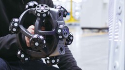
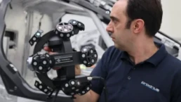
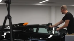
The Zeiss Comet scanner used for this project is a Structured Light scanning system for applications ranging from small, precision components to large tools, dies and vehicles. The Comet produces dense, point cloud data, which permits inspection (metrology) and reverse engineering. This scanner has an adjustable measuring volume of 75 × 75 × 50 to 900 × 600 × 600 mm, and accuracy of up to ±0.005 mm. Each view or “scan” can measure up to about 11 million X-Y-Z points. With large objects or objects with complex surface geometry it is necessary to take several measurement positions to ensure that all surfaces are recorded. There is no limit to the number of views or “patches” that can be recorded per object other than computer memory. After the scan, the patches are globally aligned to form one 3D point cloud.
Before scanning, the engine was drained and thoroughly cleaned, as the resolution of the scanner is such that dirt particles, scratches and other undesirable residue will show up in the scan data. After removal of most of the internal components (crankshaft, pistons, transmission, etc.), the external visible components were re-assembled. For the scanning, the engine was placed on a high-accuracy rotary table, of which the position is tracked to enable automatic alignment of the different scan patches. For the complete assembly, 153 patches were created, resulting in a scan data set of 4 GB. This scan data set was then reduced in size by removing overlapping points and connecting the remaining points with triangles.
This triangulated file, called an STL file, is a facetted representation of the scan geometry 1.5 GB in size (30 million triangles). As parts of the bolted-on accessories cast a shadow on the engine during scanning, large areas are not captured during the scanning process. For example, the backside of the water pump is not visible to the scanner and therefore will leave a gap in the data. To ensure completeness, the engine was disassembled and each component was scanned separately. STL files were created and then matched (best fitted) to the assembly file, to ensure correct positioning in 3D space. The individual STL files were then brought into Geomagic Design X Software from 3D Systems to fill in gaps of areas still missed during the scanning process. The gap-filling process is essential because completely closed geometry is needed to create a solid for use in Solidworks.
Bringing the STL files in Solidworks was not a viable option at the time, so Nurbs surfaces were created outside Solidworks and then imported as parasolids. To create the Nurbs surfaces, Geomagic automatically generated a network of splines on top of the STL files to approximate the geometry. From this network of splines, Nurbs surfaces are created. This method is efficient and reduces the file sizes to more manageable levels. As a final step, the surface patches are “sewn” together to form a closed solid CAD model.
This solid, constructed in Nurbs Surfaces, represents the engine as is, including any flaws there might be in the engine’s surfaces when scanned. Consequently, machining inaccuracies, worn areas, dents and scratches, etc., will be part of the model unless further steps are taken. As the goal is to be able to use the CAD models as a reference, the attachment points for frame, intake manifold and exhaust manifold need to be free of defects. They are therefore modelled in separately. Where, for example, a bolt hole would exist, a cylinder would be fitted to the scans. Solidworks can recognise the cylinder and use this as reference to which other geometry can be easily built upon.
All models are exported from the Geomagic software into the neutral parasolid format, which Solidworks can read. As all models are already in the correct position they can be loaded as assembly in Solidworks. The total size of the complete GSX-R600 engine Solidworks assembly file is about 500 MB, requiring about 1.5 GB memory when loaded in Solidworks. Although the size of the file was not an issue for any of the computer workstations in use, it is possible to suppress any of the components in the subassembly to focus on, for example, the cylinder head. To verify that the dimensions of the attachment points are correct, the solid model is also used to program the Zeiss Contura CMM and re-measure these points on a second, still-assembled engine. The solid model was then updated in Solidworks to reflect these CMM values as needed.
Soon after the FSAE community understood the capabilities of Bolton Works, requests were made for other detailed engine makes and models. Ten different engine types have been modelled to date, each with increasing level of detail.”
“A lot of the motivation for me personally was that we were such a small operation,” James Pershken says. “Basically everyone is trying to do a lot of things, and it really helped me kind of offload some of this monotonous work from my plate and be able to help out in other areas.”
Mr. Pershken is not talking about robotics or sophisticated software here, but something a little less obvious: fixturing for coordinate measurement machine (CMM) inspection. As a mechanical quality engineer at Cincinnati Inc. (CI), he manages the CMM inspection of machined parts for the company’s 3D printers. The benefits outlined above came from actually using those very same 3D printers to make custom CMM fixtures that, in turn, support the manufacture of new printers.
New Valence Robotics (NVBots for short) was a Boston-based manufacturer of polymer 3D scan printers, founded by a group of Massachusetts Institute of Technology engineers and acquired by CI in late 2017 to form the NVBots Business Unit. According to NVBots founder AJ Perez, the company was started in 2014 with a focus on automating and streamlining 3D printing by connecting printers to the cloud and optimising engineering workflow. Its NVPro 3D printer was rebranded by CI as the Small Area Additive Manufacturing (SAAM) machine in 2016. Mr. Pershken now works in the NVBots Business Unit within CI.
CI SAAM 3D printers feature a number of machined components that require CMM inspection. Pershken uses an entry-level CMM that has to be programmed by manually moving the probe to identify the datums so that the machine can determine the part axes and execute the program correctly. For a part that uses conventional off-the-shelf fixturing, it takes time and a fair bit of skill to set up a part on the table and then to perform the manual hits with the probe.
3D Printer Parts, 3D-Printed Fixtures
While working with one fairly complex machined part, Mr. Pershken had the idea to 3D print fixtures instead of using off-the-shelf items and a pegboard. That part (pictured above) is an aluminium bearing block that goes into the 3D scan printer gantry. Two slots hold the idler bearings around which the belt is routed. The components like this that make up the 3D scan printer frame are the most critical to measure correctly because they most directly affect how accurate the final printer will be, he says. On this bearing block, the tightest tolerance is a roughly 30-micron window for the pin that supports the bearing.
In inspection, the bearing block needed eight hits in each axis for a total of 24 manual hits. “One day I was just sick of putting the manual datums in again,” Mr. Pershken says. This frustration led him to create plastic fixtures using an CI SAAM 3D printer that would hold the part instead.
To design this fixture for 3D printing, Mr. Pershken says he “hacked” the injection-mold environment of a CAD program to create one half of a mold that could positively retain the part. To make the mold design work as a fixture, he then removed some material and added features such as a standard base that would fit on the CMM table.
The 3D-printed fixture is designed to allow parts to drop in place without clamps or screws. To hold the bearing block, Mr. Pershken made use of one of its features: a long slot, visible in the photo above. The mould-design software generated a solid protrusion to fill this slot, but Mr. Pershken split it into four pieces. When 3D-printed in polylactic acid (PLA) thermoplastic, this feature has enough flex to hold the part securely in place without marring it. As a result, the fixture only obscures one noncritical face of the bearing block, enabling Mr. Pershken to measure the remaining five faces with one fixtur setup: “I can just load them up, hit ‘go’ and do some other work while it’s running.”
Setting up the 3D-printed fixture simply required calibrating the CMM probe on the reference sphere, mounting a bearing block on the fixture, and then measuring all three planes manually to give the machine a reference point and direction. Subsequent parts can then be placed and measured with the press of a button. Parts placed on a 3D-printed fixture are not going to be in exactly the same position every time, but they do not need to be. “As long as it’s close enough and the CMM gets the part datums correctly, it’ll run just the same,” Mr. Pershken says.
Saved Effort and Reduced Cost
“With cycle times of just a few minutes (it takes only 1 to 2 minutes for the CMM to measure the bearing block for instance), a 3D-printed fixture is “not a huge time saver,” Mr. Pershken says, “but it is a huge effort saver.”
“Fixturing the parts conventionally would involve the use of a fixture kit, which may cost $1,000 for a basic option, and it would not be a drop-in-place solution. “You’ll have to introduce a clamping force somewhere,” Mr. Pershken says, which runs the risk of damaging the part. “It’s going to require somewhat more of a skilled operator and little more time in the setup.”
Mr. Pershken now has a collection of about 10 3D-printed fixtures, some of which have been in use for as long as 2 years without needing replacement. Since the fixtures essentially get checked automatically with each CMM cycle, Mr. Pershken tests them periodically but has not found a need to worry much about loss of accuracy. “I haven’t noticed any slop in them or any bad measurements,” he says. “I haven’t had to replace one yet.”
Many of the machined parts for the CI SAAM printer are fairly simple cylinders and plates that would not benefit much from a custom 3D-printed fixture. However, for those that have an intermediate to complicated geometry and require high accuracy, such as parts for the 3D printer frame, the 3D-printed fixtures simplify the CMM process significantly. As CI begins to produce more of its printer parts through machining and sheet-metal forming, Mr. Pershken plans to continue 3D-printing fixtures to support CMM inspection.


Revving Up Innovation: T3DMC Becomes Prodrive’s Official 3D Scanning Partner
Explore how our 3D scanning partnership with Prodrive is accelerating advancements in motorsport and driving innovation.


Preserving History With 3D Scanning Technology: The Mk2 Cockle Canoe, Operation Frankton
Preserving history with SIMSCAN. Capturing 3D data of WW2's unsung hero, Operation Frankton's Mk2 Cockle Canoe.